 Suppose you have a datacenter with a need of policy-based separation between specific devices. There’s a few ways to do this – start by placing them in different VLANs from each other. You can run an ACL on the SVI, and bam! — they can’t talk anymore. What do you do when you have so many devices, that messing with an ACL is a massive pain in the ass? You could make a firewall the gateway on those VLANs so that your firewall policy controls access to/between these VLANs. What if you have 100Gbit uplinks, in a Layer 3 Leaf/Spine topology (L3LS from here on out)? Getting a firewall with that level of throughput isn’t cheap. If you have the ability to group devices with similar roles (eg. DMZ, Internal, Application) you could use VRF-Lite to separate devices at Layer 3.
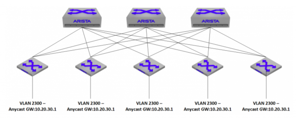
The problem with VRF-Lite is that it’s locally significant. It needs to be built on each switch that participates in these VRFs, and there needs to be an interface that is a member of a VRF on each side of inter-switch links in order to extend it between switches. I ran into an issue recently where I wanted to extend 10+ VRFs across my entire environment. Normally, I’d run MPLS to do this, but Arista gear at the time didn’t support any kind of L3VPN functionality (note: Now that EVPN has released, this config can be simplified greatly). One of my requirements when building this out, was that I needed VXLAN support – specifically, VXLAN routing. I wanted each Leaf switch to be able to host an anycast gateway for the VXLAN participating VLANs in order to get the packets out into the fabric, and to their final destination as quickly as possible.
VXLAN routing has the ability to use overlay VRFs, meaning that it can effectively extend VRFs between switches without having to extend VRF-Lite between switches with physical interfaces – the VXLAN packets are simply dumped to the VLAN that the VNI belongs to, and can be routed with standard layer 3 beyond that. There were a couple of trade-offs with this.
One: Every switch that needed to host a VRF, also needed to participate in VXLAN routing in some way. This wasn’t ideal, as (at the time) Arista border leaves had the capability to either hold an internet-scale routing table or run VXLAN routing.
Two: The Jericho chipsets that we were using didn’t officially support VXLAN routing yet. This was the main no-go.
As a workaround, I had to come up with a way to extend these VRFs across the entire datacenter. Thus, the subinterface fiesta is born.
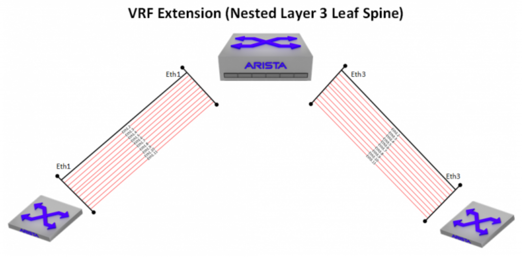
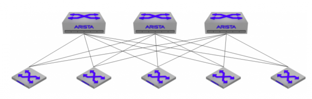
With a L3LS topology, every leaf switch has a layer 3 connection to every spine switch, and subinterfaces can be leveraged as a lamprey-like means of attaching VRF-lite segments in order to hitch a ride over to the other side. While this can work, traditionally, it doesn’t scale well. Giving each spine a /24 and allocating /31s for the leaf-spine links can quickly get out of hand when you have multiple VRFs riding over it. With each spine having a connection to 8 leaf switches and just 4 VRFs extended over, you’re looking at 64 IP addresses per spine – scale the VRFs up much higher, and you’ll see some real pain.
One advantage to L3LS, is that the transit links between leaf and spine really don’t matter as long as you have a routing protocol (eBGP in this case) to signal the actual leaf routes to the spines. You don’t even need to advertise them into the BGP table if you don’t have a reason to (a couple caveats with that, which I’ll go into later). This meant that instead of needing 64 IP addresses, I could use 2 IP addresses for the routed link (/31 on each end), and simply re-use the same IP addresses within every VRF riding over it. Establish a BGP peering between leaf and spine within each VRF, and you’re good to go.
This satisfies the means of extending VRF-Lite between switches, but how do you route outside the VRF without any kind of route leaking? You need a central point of routing. With multiple 100Gbit uplinks, a single firewall wasn’t an option to host the L3 head-ends, but with a lot of traffic being soaked up by full east/west connectivity within the VRF, there’s way more leniency in throughput. This device doesn’t have to be a firewall, technically any Layer 3 device can do it. In our case we wanted a simplified firewall policy to control access, since we had a need to separate these VRFs to begin with.
One of the caveats I mentioned earlier is that any connection that uses the routed link address as the source-ip will fail, since there’s no return route to it. To work around this, you could build a loopback address on each switch, advertise it into BGP, and source any traffic that you need from it – radius, http, ssh, etc…
The other issue is that traceroute may look weird to those that aren’t expecting it, as sometimes you can be hashed out the same physical leaf<->spine uplink that shares an IP, which could look like a loop to the untrained eye.